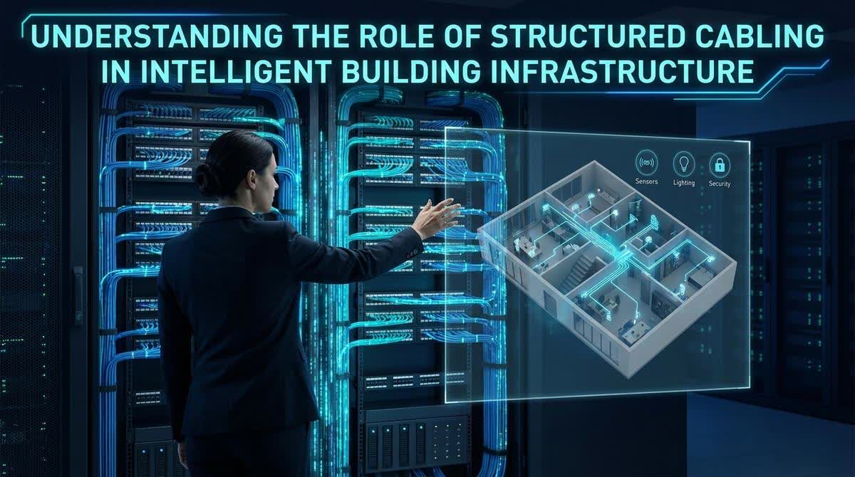
Understanding the Role of Structured Cabling in Intelligent Building Infrastructure
If ELV systems are the organs of an intelligent building, structured cabling is the nervous system, the essential infrastructure that enables communication between all components.
Yet, structured cabling is often treated as a commodity, specified with minimal thought and installed with limited attention.
This approach is a strategic error with significant consequences.
In the age of intelligent buildings, the structured cabling infrastructure must support not only current needs but also future capabilities.
Understanding its role, design principles, and implementation requirements is essential for building owners, project planners, and facility managers.
The Strategic Importance of Structured Cabling
Foundation for All IP-Based Systems
Almost every ELV system now relies on IP-based communication:
- CCTV systems operate over IP networks
- Access control systems use IP communication
- BMS increasingly relies on IP protocols
- VoIP and IP telephony require IP infrastructure
- WLAN access points connect over IP
- Digital signage relies on IP distribution
- AV systems are migrating to AV-over-IP
Without a robust structured cabling infrastructure, these systems cannot deliver their full potential.
Long-Term Investment
Structured cabling typically has a lifespan of 15-20 years, significantly longer than most active equipment.
Decisions made about cabling today will impact building operations for decades.
Upgrading cabling later is disruptive and expensive, making initial investment in higher-grade infrastructure a sound long-term strategy.
Flexibility and Adaptability
A well-designed structured cabling system supports reconfiguration without rewiring.
When offices are rearranged, systems are upgraded, or new technologies are adopted, the cabling infrastructure should accommodate these changes without major modification.
Critical Infrastructure
Structured cabling supports safety and security systems, fire alarms, access control, CCTV, and voice evacuation.
Reliability isn't optional; it's essential. Failure can have safety implications.
Standards: The Foundation of Structured Cabling
TIA/EIA-568 Series
The TIA/EIA-568 standard is the primary reference for commercial building cabling:
TIA/EIA-568.0-D:
- General cabling requirements
- Topology and architecture
TIA/EIA-568.1-D:
- Commercial building cabling
- Installation practices
TIA/EIA-568.2-D:
- Balanced twisted-pair cabling
- Component requirements and testing
TIA/EIA-568.3-D:
- Optical fiber cabling
- Component requirements and testing
ISO/IEC 11801 Series
The international counterpart to TIA/EIA-568, ISO/IEC 11801 provides global standards for structured cabling.
Key Requirements
Maximum Horizontal Cable Length:Â 90 meters (295 feet) from telecommunications room to outlet
Maximum Total Channel Length:Â 100 meters (328 feet), including patch cords and equipment cables
Cable Categories:
- Category 5e: 1 Gbps up to 100m
- Category 6: 1 Gbps up to 100m, 10 Gbps up to 55m
- Category 6A: 10 Gbps up to 100m
- Category 7: 10 Gbps up to 100m, shielded
- Category 8: 25/40 Gbps up to 30m (data centers)
Fiber Types:
- OM3: 50/125μm, 10 Gbps up to 300m
- OM4: 50/125μm, 10 Gbps up to 550m
- OM5: 50/125μm, 40/100 Gbps up to 150m
- Single-mode: 100 Gbps+ over long distances
Structured Cabling Architecture
Hierarchical Design
Campus Level:
- Connects buildings on a campus
- Typically uses single-mode fiber
Building Level:
- Connects telecommunications rooms within a building
- Uses fiber or copper depending on distance
Floor Level (Horizontal):
- Connects telecommunications room to outlets on the same floor
- Primarily copper cabling (Category 6A recommended)
- Maximum 90 meters from TR to outlet
Work Area:
- Connects outlets to user devices
- Patch cords and equipment cables
Key Components
Telecommunications Rooms (TR/IDF):
- Distribution point for the floor
- Contains patch panels, switches, and cable management
Main Distribution Frame (MDF):
- Primary connection point for the building
- Contains backbone connections and main switches
Backbone Cabling:
- Connects MDF to TRs
- Typically fiber optic for high performance
- Connects floors to the data center
Horizontal Cabling:
- Connects TRs to outlets
- Typically copper Category 6A
- Home runs to the TR (no splicing)
Outlets (Faceplates):
- Termination point in the work area
- Typically two outlets per work area
- Can be configured for voice and data
Patch Panels:
- Termination point in the TR
- Supports flexible connections
- Can be copper or fiber
Cable Management:
- Supports organized cabling
- Reduces strain on cables
- Enables future changes
Design Considerations for Intelligent Buildings
Capacity Planning
Current Needs:
- Estimate number of outlets per work area
- Consider 2-3 outlets per work station
- Plan for WLAN access points
- Consider AV and digital signage outlets
Future Growth:
- Plan for 20-30% growth in outlet requirements
- Allow space in telecommunications rooms for growth
- Install higher-grade cable to support future speeds
Pathway Design
Vertical Pathways:
- Distribute cabling between floors
- Typically using cable trays
- Consider multiple pathways for redundancy
Horizontal Pathways:
- Distribute cabling on each floor
- Use cable trays, conduits, or raised floors
- Plan for separation from power cables
Tray and Conduit Sizing:
- Plan for 50% fill capacity maximum
- Allow for future additions
- Consider cable category and diameter
Telecommunications Room Design
Space Requirements:
- 12-20 square meters minimum
- Consider active equipment space
- Allow for working space
Environmental Requirements:
- Temperature: 64-75°F (18-24°C)
- Humidity: 30-50%
- Adequate ventilation
- Clean environment
Power Requirements:
- Dedicated circuits for equipment
- UPS support for critical equipment
- Consider PoE (Power over Ethernet) needs
Category Selection: Making the Right Choice
Category 6
- Supports 1 Gbps to 100m
- Supports 10 Gbps to 55m
- Suitable for most office environments
- Lower cost than Category 6A
Category 6A
- Supports 10 Gbps to 100m
- Future-proof for 10 Gbps
- Suitable for hospitals, universities, high-density offices
- Higher cost, larger cable diameter
Category 7/8
- Supports 25/40 Gbps
- Shielded to reduce interference
- Suitable for data centers and high-performance environments
- Significant cost premium
Fiber Optic
- Supports highest speeds and distances
- Future-proof for decades
- Suitable for backbone and high-performance applications
- Higher installation costs
Recommendation for Intelligent Buildings:
- Horizontal:Â Category 6A (future-proofing for 10 Gbps)
- Backbone:Â Single-mode or OM4 fiber
- Work Area:Â Category 6A patch cords
- WLAN:Â Category 6A to support PoE and future upgrades
Installation Best Practices
Cable Pulling
- Use cable lubrication for long runs
- Avoid excessive tension (max 25 lbs for Category 6A)
- Maintain bend radius (4x cable diameter minimum)
- Use proper pulling eyes to avoid kinking
Cable Management
- Use Velcro ties rather than zip ties
- Label cables clearly at both ends
- Maintain separation from power cables
- Support cables properly in trays and racks
Termination
- Follow T568A or T568B standard consistently
- Use proper punch-down tools
- Maintain twist ratio as close to termination as possible
- Test each termination immediately
Cable Protection
- Protect from construction traffic
- Avoid sharp edges in trays and conduit
- Use proper bushings and fittings
- Maintain environmental conditions
Testing and Commissioning
Certification Testing
Required Tests:
- Wire map (continuity, opens, shorts)
- Insertion loss (attenuation)
- Return loss (impedance matching)
- Near-end crosstalk (NEXT)
- Power sum near-end crosstalk (PSNEXT)
- Equal level far-end crosstalk (ELFEXT)
- Power sum equal level far-end crosstalk (PSELFEXT)
- Propagation delay
- Delay skew
Test Equipment:
- Fluke DSX-8000 or similar certified tester
- 24 AWG patch cords for testing
- Proper test adapters
- Calibrated equipment
Acceptance Criteria:
- Pass all tests per TIA/EIA-568
- Document all test results
- Provide certified test reports
Documentation Requirements
Test Reports:
- Individual test results for each permanent link
- Summary reports for each test batch
- Certification of compliance with standards
Cable Labeling:
- Label both ends of each cable
- Use consistent labeling scheme
- Include in as-built documentation
Drawings:
- Floor plans with outlet locations
- Riser diagrams with cable types
- Telecommunications room layouts
The AllandMuchMore Advantage
At AllandMuchMore, we understand that structured cabling is not a commodity, it's a strategic investment in building intelligence.
Our approach is based on:
Comprehensive Design
We work with building owners and designers to create structured cabling solutions that support current needs and future growth.
Quality Installation
Our experienced teams follow best practices for cable installation, ensuring optimal performance and reliability.
Thorough Testing
We certify every connection with certified test equipment, providing comprehensive documentation for building operators.
Future-Ready Solutions
We recommend higher-grade cabling to support future bandwidth requirements, protecting your investment over decades.
Integration Support
We understand how structured cabling supports all ELV systems, ensuring seamless integration across your building.
In the End :
Structured cabling is the foundation of intelligent building infrastructure.
Understanding its strategic importance, design principles, and installation requirements is essential for building owners, project planners, and facility managers who want to maximize the value of their buildings.
Investing in high-quality structured cabling pays dividends through:
- Support for current and future systems
- Flexibility for building reconfiguration
- Reduced troubleshooting time
- Higher reliability
- Improved building value
At AllandMuchMore, we bring decades of experience in structured cabling design and installation to every project.
When you work with us, you're building for the future.