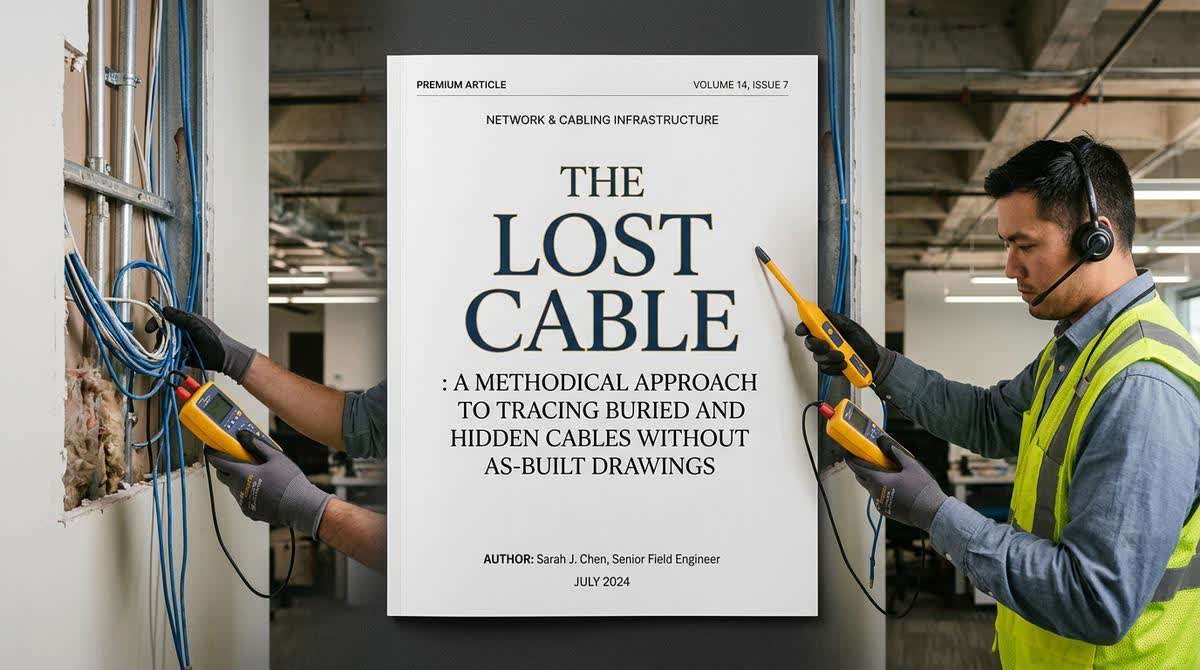
Every building project concludes with a perfect set of as-built drawings that accurately reflect every meter of cable installed. But anyone who has worked in this industry for more than a few years knows this is rarely the case. As-built drawings are often incomplete, inaccurate, or simply lost. This transforms even a simple task like tracing a single data, control, or fiber optic cable into a significant technical challenge.
When you are standing in a building, staring at a network of cable trays and conduits with no documentation, the task can seem overwhelming. However, by adopting a structured, multi-phased approach that combines site investigation, physical tools, and deductive reasoning, you can trace almost any cable. This is not guesswork; it is a systematic process of elimination that leverages an understanding of cable physics, construction history, and human nature. This guide will walk you through that process, turning a daunting task into a manageable, methodical investigation.
Phase One: The Art of the Site Investigation and "Tribal Knowledge"
Before you connect a single piece of test equipment, your most valuable tool is your ability to observe and ask questions. This phase is about gathering intelligence from the environment and from the people who know it best. The physical layout of a building is rarely random, and the installation practices of the past tend to follow predictable patterns.
Intelligence Source Key Questions to Ask What to Look For
Maintenance Staff & Technicians Who has worked here the longest? Do you remember any major works? The "institutional memory" of the building. They may recall how cables were originally run or know of undocumented modifications.
Walk the Path Where would I have run this cable if I were the installer? Follow the path of least resistance. Installers always seek the easiest route: cable trays, ceiling voids, riser shafts, and mechanical rooms.
Visual Clues Are there any signs of previous work? Look for patches in walls or ceilings, spare conduits, or junction boxes that seem out of place. These are often markers of cable paths.
Construction Logic How was this building built? Cables typically run vertically through riser shafts and horizontally through ceiling voids or raised floors. Understanding the building's structure helps predict cable paths.
نصيØØ© الخبير: لا تستهين أبداً بقوة "المعرÙØ© المØلية" (Tribal Knowledge). Ùني الصيانة القديم الذي عمل ÙÙŠ المبنى لسنوات هو أغلى مورد لديك. اسأله واسمع جيداً، Ùغالباً ما يكون لديه خريطة ذهنية للمكان لا توجد ÙÙŠ أي وثيقة.
Phase Two: The Diagnostic Toolkit and Signal Tracing
Once you have a general idea of the path, it is time to bring in the tools. The objective is to confirm your hypothesis and pinpoint the exact route. Choosing the right tool for the job is critical here.
Tool 1: The Tone Generator and Probe (Fox and Hound)
This is the most versatile and indispensable tool for cable tracing. It works by injecting an audio frequency signal onto the cable. A separate probe is then used to detect this signal through walls, ceilings, and floors.
How to Use: Connect the tone generator to the cable at its known endpoint. Use the probe to trace the signal path along the suspected route. The signal will be strongest when the probe is directly over the cable.
When to Use: This is effective for tracing cables through drywall, plaster, and ceiling voids. It is generally ineffective through thick concrete or metal conduits.
Pro Tip: If you are tracing a multi-pair cable, connect the tone to a single pair. This allows you to differentiate it from other cables in the same bundle.
Tool 2: The Time-Domain Reflectometer (TDR)
A TDR is a more sophisticated tool that measures the time it takes for a signal to travel down a cable and reflect back. It can accurately determine the distance to a fault (like a cut or a short). This is the ultimate tool for "worst-case" scenarios where the cable is suspected to be broken or buried under concrete.
How it Works: The TDR sends a pulse down the cable. When that pulse encounters a change in impedance (like a cut, a splice, or the end of the cable), it reflects a portion of the signal back. By measuring the time it takes for this reflection to return, the TDR calculates the distance to the fault.
Formula: Distance (in meters) = (Propagation Velocity x Time) / 2
When to Use: This is the tool of choice for underground cables, cables in concrete, or when the cable is completely "dead" and you need to locate a break.
Tool 3: The Multimeter (for Copper Cables) and the "Loop Resistance Method"
If you have access to both ends of a multi-core copper cable, you can use the multimeter to trace it and even estimate the distance to a break. This is an old-school but highly effective method.
The Loop Resistance Method:
At the far end of the cable, short two wires together.
At the near end, measure the resistance across that pair. This is the resistance of the entire loop (cable out and back).
Record this value. Now, move along the suspected path to a mid-point junction box or testing point.
At the mid-point, disconnect the cable and measure the resistance of the loop again.
By comparing the resistance values (which are proportional to length), you can determine if the cable still runs to the far end or if it is broken between the mid-point and the far end.
نصيØØ© الخبير: هذه الطريقة تعتمد على قانون أوم (R = ÏL/A). بÙرض أن المقطع العرضي للكابل ثابت، Ùإن المقاومة تتناسب طردياً مع الطول. هذه الطريقة دقيقة للغاية إذا تم تنÙيذها بعناية واستخدمت Ù„ÙØص أزواج الكابلات النØاسية (مثل كابلات الإنذار أو الهواتÙ).
Phase Three: The "Divide and Conquer" Tracing Strategy
When you have a long cable run with many unknowns, the most efficient approach is a variant of the binary search algorithm. This strategy allows you to locate a break or a cable's path with minimal physical exploration.
Step Action
1 Identify the Mid-Point. Determine the approximate halfway point of the cable's suspected route. This is a point where you can physically access the cable.
2 Gain Access. Open the junction box or cable tray at the mid-point to expose the cable.
3 Test from the End. If you have the far end of the cable available, connect a tone generator to it. Use your probe at the mid-point to verify if you are tracing the correct cable and if the signal is strong.
4 Verify Continuity. If you are testing for a break, use the multimeter to check continuity of the cable at the mid-point. If the cable is broken between your position and the far end, you will see an open circuit.
5 Narrow the Search. Based on your test results, you can now determine which half of the cable contains the fault. If the fault is in the second half, move to the mid-point of that section. Repeat this process until you have narrowed the search area to a manageable, physical length of cable to inspect or repair.
نصيØØ© الخبير: هذه الاستراتيجية تØول مشكلة "إيجاد إبرة ÙÙŠ كومة قش" إلى سلسلة من العمليات الثنائية المنطقية. بتقسيم المساÙØ© إلى نصÙين ÙÙŠ كل مرة، يمكنك تØديد موقع العطل بدقة متناهية وبأقل عدد ممكن من المØاولات الÙيزيائية. هذا يوÙر وقتاً وجهداً هائلين ÙÙŠ المشاريع الكبيرة.
Phase Four: The Physical Identification (The "Surgical" Approach)
After you have traced the cable and narrowed down the location of the fault to a specific area, the final step is to physically access it. The goal here is to cause the least amount of damage to the building structure.
Precision, Not Demolition: Start with a small pilot hole at the suspected location. Use a borescope (endoscope) if available to confirm the cable's presence and condition before making a larger opening.
Tagging and Documentation: Once you have identified the cable, tag it clearly at both ends and at the access point. Update your as-built drawings immediately. This ensures that the problem is not repeated on the next project.
The Final Lesson: Document, Document, Document
The process of tracing a lost cable is a testament to the importance of documentation. Every time you successfully identify a cable, document its path. Update the cable schedule and the riser diagram. This is not just for the current project; it builds a knowledge base that will save hours of work for your team in the future. By following this systematic, phased approach, you transform a chaotic, stressful task into a controlled, solvable engineering problem. This is the mark of a true field expert. At AllandMuchMore, we treat every cable trace as an opportunity to build better documentation and deliver greater value to our clients.